This is a simple note on Crow’s Foot notation used in Entity Relationship (ER) Diagrams.
An ER diagram visually represents entities, their attributes, and the relationships between them.
The main concepts we will cover in this Article:
- Entity
- Relationship
- Crow’s Foot notation
Entity
An Entity represent real-world object or concept about which data can be stored in a database, such as Person, Car, or Author. In a relational database, an entity is represented by a table.
An Entity has attributes that describe its properties. For example, a person entity might have attributes like “id”, “first_name”, “last_name,” and so on.
Relationship
A relationship denotes how entities are associated with each other in a database. Think of them as a verb.
There are three common types of relationships:
- One to One (1:1): One record is associated with at most one record in another entity.
- One to Many (1: N): One record can be associated with multiple records in another entity.
- Many to Many (N : N): Multiple records in one entity can be associated with multiple records in another entity.
Crow's Foot Notation
Crow’s Foot notation is a way of representing relationships among entities in an ER diagram.
To understand it, we need two concepts:
- Cardinality: How many records of one entity can be associated with another record?
- Optionality: Is this relationship optional or mandatory?
Below are the symbols used in Crow’s foot notation to represent relationships between two entities.
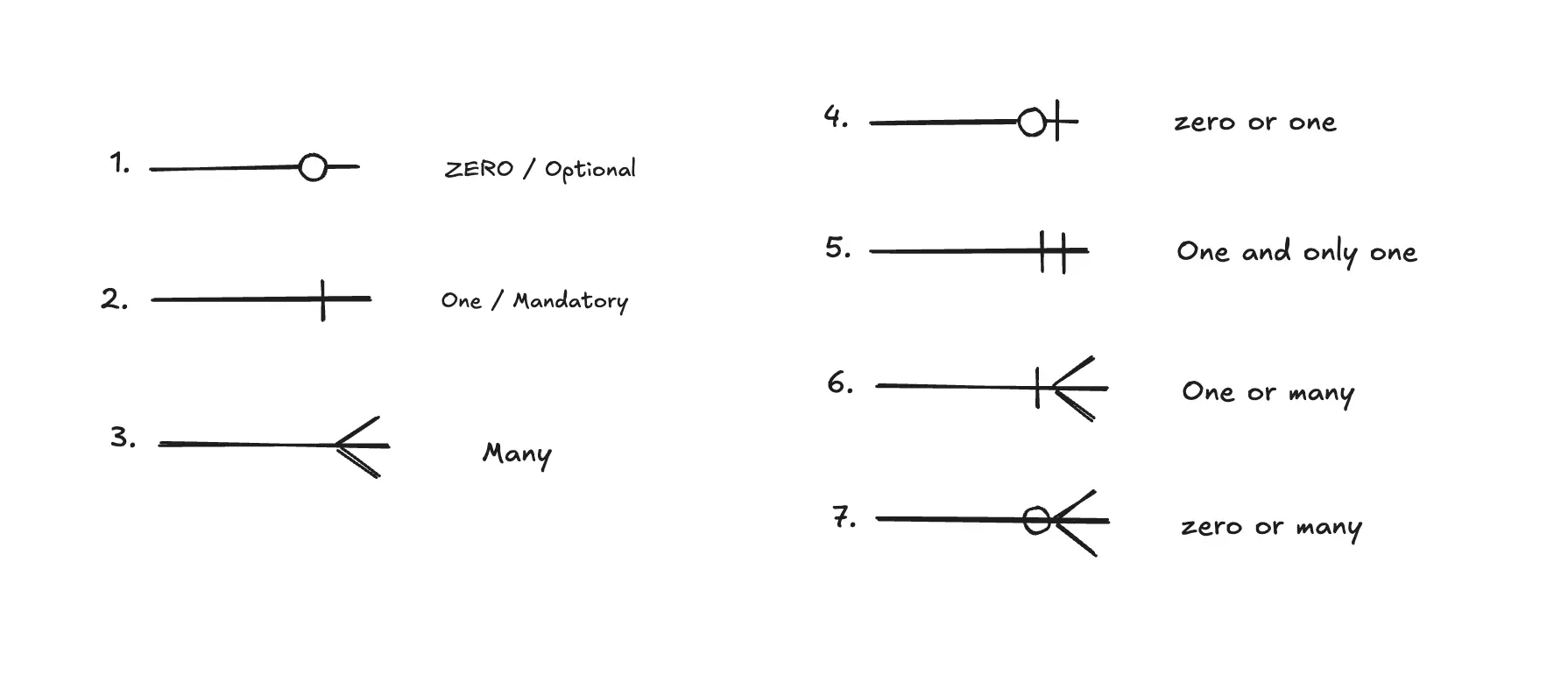
Entity Relationship (ER) Diagram
Let’s understand these symbols by creating an ER diagram of an airport system.
Our system has the following entities:
- Airline
- Flight
- Passenger
- Check-in
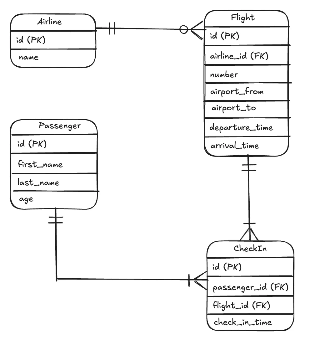
Here are the relationships represented in the diagram:
- Airline and Flight: An airline can have zero or many flights, but a flight belongs to exactly one airline. This is a one-to-many relationship.
- Flight and Passenger: A flight can have many passengers, and a passenger can travel on many flights. This is a many-to-many relationship.
- Passenger and Check-in: A passenger can have multiple check-in records, but each check-in record belongs to exactly one passenger.
- Flight and Check-in: A flight can have multiple check-in records, but each check-in record belongs to exactly one flight.
The Check-in entity creates a link between passengers and flights. In a relational database, it works as a linking table for a many-to-many relationship between Passenger and Flight.
I hope this note helps you in understanding an ER diagram and also designing a database that represents how data is connected in the real world.